



High Precision Benchtop SMU
S2035H
Single-channel High-precision SMU
The S2035H is a high-precision, compact, cost-effective, single channel benchtop Source/Measure Unit (SMU) with a wide range of voltage source (± 200V) and current source (± 1A DC and ± 3A pulse) capabilities. It provides the excellent accuracy with 6 ½ digits display resolution (minimum 1fA/100nV) and nice graphical user interface (GUI) on superior color LCD.
Features

High Range
Range: ±200 V, ±1 A(DC), ±3A (pulse)
High Resolution
The minimum measurement resolution can reach 1 fA/100 nV
High Sampling Rate
Supports up to 1M ADC sampling rate
Threshold Trigger
Hardware high-speed IO, capable of threshold triggering, enabling efficient interaction between output measurement values and user systemsFunctions and Advantages

DC I-V Out Capability

|
Voltage Programming Accuracy |
Range |
Programming Resolution |
Accuracy (1 Year) ± (% reading+ offset) |
Typical Noise (RMS) 0.1 Hz-10 Hz |
|
±200 V |
100 μV |
0.03%+10 mV |
0.4 mV |
|
|
±40 V |
10 μV |
0.03%+2 mV |
100 μV |
|
|
±20 V |
10 μV |
0.03%+1 mV |
50 μV |
|
|
±2 V |
1 μV |
0.03%+100 μV |
10 μV |
|
|
±0.6 V |
100 nV |
0.03%+50 μV |
2 μV |
|
|
Temperature Coefficient |
±(0.15 × accuracy)/℃ (0℃-18℃,28℃-50℃) |
|||
|
Settling Time |
<50 μs (typical) |
|||
|
Overshoot |
< ±0.1% (Normal; Step is 10% to 90% range, full-scale, resistive load) |
|||
|
Noise 10Hz-20MHz |
20V voltage source,1A resistive load, <5 mVrms |
|||
|
Current Programming Accuracy |
Range |
Programming Resolution |
Accuracy (1 Year) ± (% reading+ offset) |
Typical Noise (RMS) 0.1 Hz-10 Hz |
|
±3 A[1] |
1 μA |
0.03% + 2 mA |
20 μA |
|
|
±1 A |
100 nA |
0.03% + 90 μA |
4 μA |
|
|
±100 mA |
10 nA |
0.03% + 9 μA |
600 nA |
|
|
±10 mA |
1 nA |
0.03% + 900 nA |
60 nA |
|
|
±1 mA |
100 pA |
0.03% + 90 nA |
6 nA |
|
|
±100 μA |
10 pA |
0.03% + 9 nA |
700 pA |
|
|
±1 μA[2] |
100 fA |
0.03% + 200 pA |
20 pA |
|
|
±10 nA[2][3] |
10 fA |
0.06% +9 pA |
600 fA |
|
|
±1 nA[2][3] |
1 fA |
0.1% +3 pA |
60 fA |
|
|
±100 pA[2][3] |
1 fA |
0.3% +1 pA |
30 fA |
|
|
Temperature Coefficient |
±(0.15 × accuracy)/℃ (0℃-18℃, 28℃-50℃) |
|||
|
Settling Time |
<100 μs (typical) |
|||
|
Overshoot |
< ±0.1% (20 V voltage range, Normal; Step is 10% to 90% range, full-scale, resistive load) |
|||
[1] 3 A range is available only for pulse mode, with typical accuracy
[2] For accurate low current measurements, triaxial cable connection is recommended. Converting the triaxial output to standard wiring will affect current measurement accuracy
[3] Condition: NPLC = 10 PLC
|
Minimum Programmable Pulse Width |
100 μs |
|
Pulse Width Programming Resolution |
1 μs |
|
Pulse Width Programming Accuracy |
±10 μs |
|
Pulse Width Jitter |
2 μs |
|
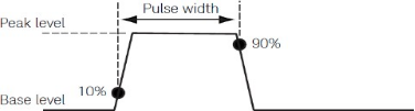
Pulse Width Definition |
The time from 10% leading to 90% trailing edge as follows |
|
Item |
Maximums |
Maximum Pulse Width |
Maximum Duty Cycle |
|
1 |
0.1 A/200 V |
DC, no limit |
100% |
|
2 |
1 A/20 V |
DC, no limit |
100% |
|
3 |
3 A/66.6 V |
1 ms |
5% |
|
4 |
3 A/160 V |
400 μs |
2% |
|
Source |
Maximum Output |
Typical Rise Time [1] |
Typical Settling Time[2] |
Test Load |
|
Voltage Source
|
160 V |
800 μs |
1.2 ms |
NO load |
|
40 V |
400 μs |
800 μs |
NO load |
|
|
20 V |
100 μs |
400 μs |
NO load |
|
|
Current Source
|
3 A to 1 mA |
90 μs |
250 μs |
Full load[3] |
|
100 μA |
120 μs |
400 μs |
Full load[3] |
|
|
1 μA |
800 μs |
1.2 ms |
Full load[3] |
|
|
10 nA |
5 ms |
20 ms |
Full load[3] |
|
|
1 nA |
10 ms |
50 ms |
Full load[3] |
|
|
100 pA |
100 ms |
500 ms |
Full load[3] |
[1] Time required for the pulse leading edge to rise from 10% to 90%
[2] Time required for the pulse to reach within 1% of final value
[3] Test conditions: Normal mode, resistive full load, voltage rises to 6 V
|
Source |
Range |
Output Settling Time[1] |
Condition |
||
|
Fast[2] |
Normal |
Slow |
|||
|
Voltage |
200 V |
<500 μs |
<1 ms |
<2 ms |
Time required to reach within 0.1% of final value at open load condition. |
|
40 V |
<200 μs |
<400 μs |
<900 μs |
||
|
20 V |
<60 μs |
<100 μs |
<500 μs |
||
|
2 V |
<50 μs |
<50 μs |
<50 μs |
||
|
0.6 V |
<50 μs |
<50 μs |
<50 μs |
||
|
Current |
3 A~1 mA |
<50 μs |
<100 μs |
<0.8 ms |
Time required to reach within 0.1% (0.3% for 3 A range) of final value at short condition. |
|
100 μA |
<100 μs |
<150 μs |
<0.8 ms |
||
|
1 μA |
<1 ms |
<1 ms |
<1 ms |
||
|
10 nA |
<10 ms |
<10 ms |
<10 ms |
||
|
1 nA |
<50 ms |
<50 ms |
<50 ms |
||
|
100 pA |
<500 ms |
<500 ms |
<500 ms |
||
[1] Output slew rate: Fast, Normal, Slow modes. Users can adjust APFC parameters according to load characteristics to achieve appropriate settling time or stability to obtain precision, and fast output characteristics
[2] Fast mode may exhibit significant output overshoot under different ranges or load conditions. For devices sensitive to overshoot, Normal or Slow mode is recommended
|
Setting |
Range |
|
NPLC |
0.00005 PLC to 10 PLC |
|
Sampling Rate |
5 sps to 1 Msps |
Add % of range using the following table for measurement with PLC < 1
|
PLC |
Range |
|||||||
|
0.6 V |
2 V |
6 V |
20 V |
200 V |
100 pA to 1 μA |
100 μA to 100 mA |
1 A to 3 A |
|
|
0.1 |
0.02% |
0.02% |
0.01% |
0.01% |
0.01% |
0.02% |
0.01% |
0.01% |
|
0.01 |
0.3% |
0.3% |
0.3% |
0.03% |
0.02% |
0.2% |
0.02% |
0.02% |
|
0.001 |
3.20% |
3.20% |
3.20% |
0.04% |
0.10% |
2.50% |
0.03% |
0.03% |
Similar recommendation

High speed communication test plays an important role in the rapid development of big data, cloud computing, 5G communication and other markets.
Semight offers various of instruments for optical Transceiver/Component testing, including wide bandwidth sampling oscilloscope, NRZ/PAM4 bit error ratio tester , burst error ratio tester, fast wavelength meter, high precise source measure unit, 400G network analyzer ,optical power meter, optical attenuator, optical switch etc. We provide cost-effective, complete solutions for optical testing.

The high-precision source measure units integrates the functions of voltage source, current source, voltmeter, ampere meter, and electronic load in one, which is widely used in high-precision IV test and measurement for various discrete components, photovoltaic, green energy, battery and other industries. Semight provides high-precision benchtop SMU and plug-in PXIe SMU of standard PXIe chassis, fully meeting the application of various test scenarios.
Details
Burn-in testing of laser is an important method to ensure the reliability of laser. Through the test of CoC or bare die, the early failure of laser caused by the defects in the process of laser production can be screened out in advance. Semight provides a complete solution from bare die to CoC, from high temperature(150℃ or higher) to low temperature (-40℃), with CoC automatic loading and unloading system, forming a complete test solution, Semight's laser chip burn-in/load/unload test system has been widely recognized by the market.
Details
The front-end test is mainly used in the wafer processing to check whether the processing parameters of the wafer products meet the design requirements or there are defects affecting the yield after each step of the manufacturing process. The back-end test equipment is mainly used after wafer processing to check whether the performance of the chip meets the requirements, which belongs to the electrical performance test. Semight provides solutions such as Wafer Level Burn In system and Known Good Die handler for SiC testing, offering the value to customer in test efficiency improvement and test cost reduction.
DetailsService hotline
Follow
Name
E-mail verfication code
Phone
Password
Confirm Password
Authorization Key
E-mail address
E-mail verification code
New Password
Confirm Password

 Datasheet
 Ask for demo