
Sampling Oscilloscope
DCA6201
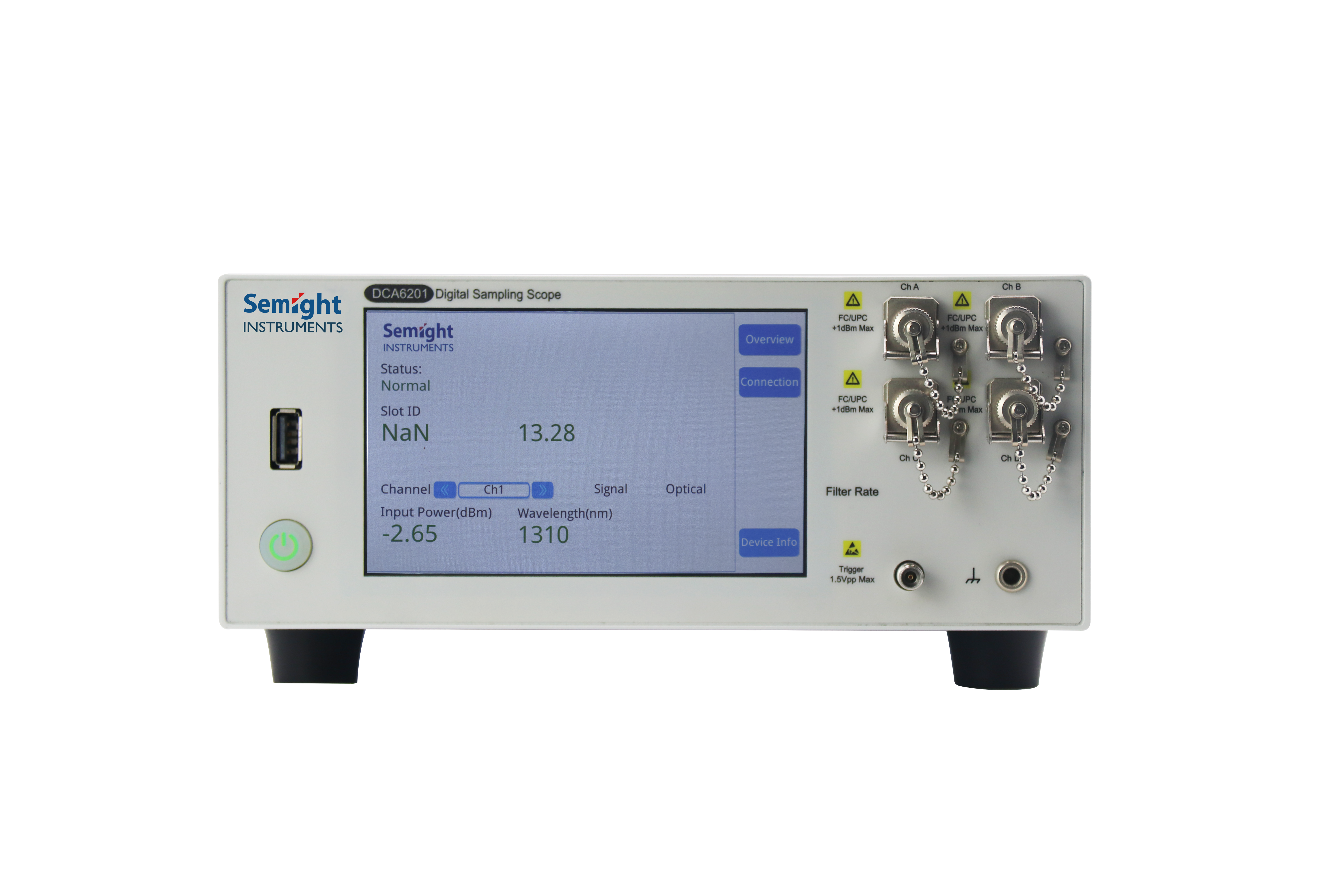
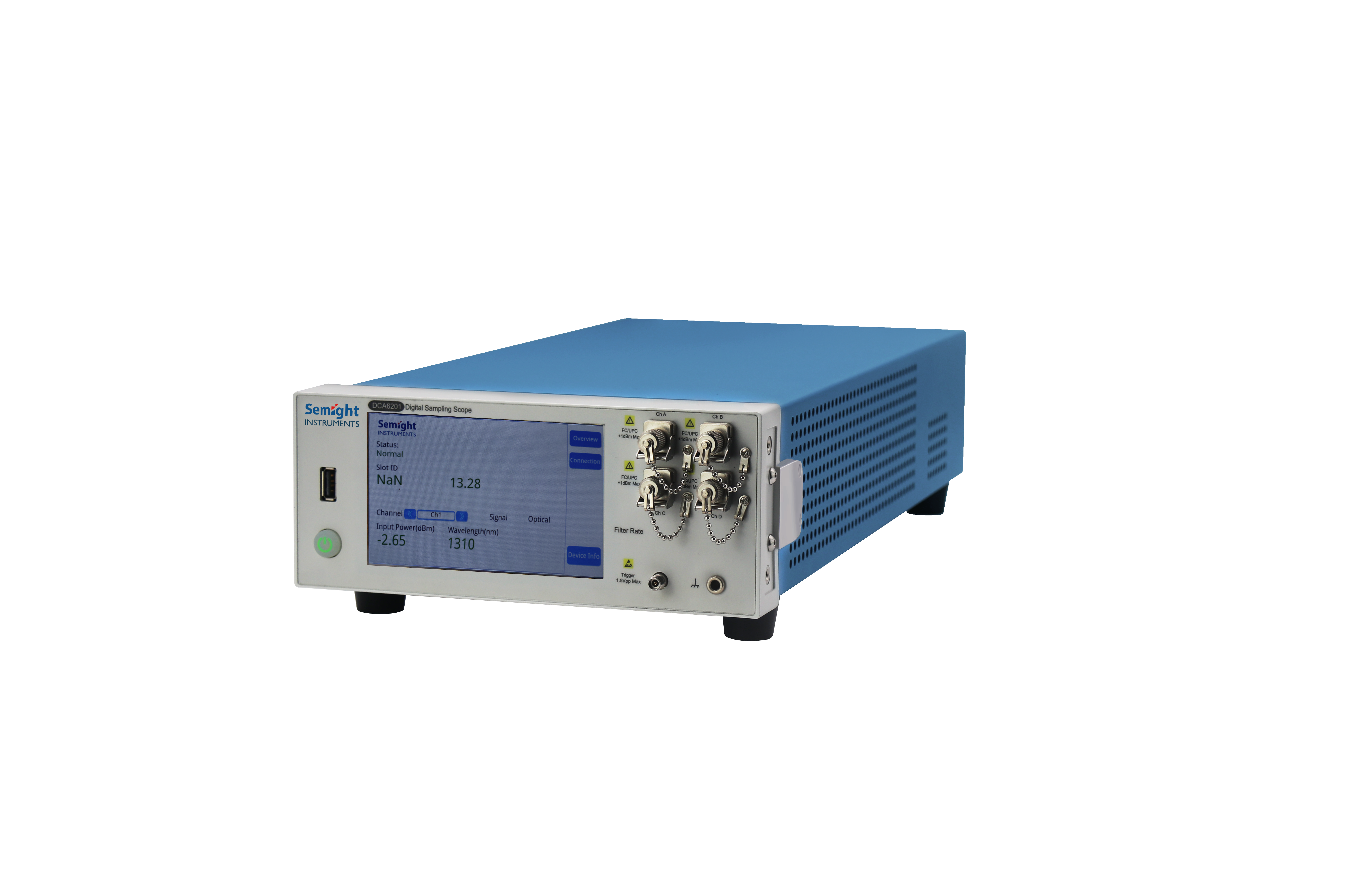
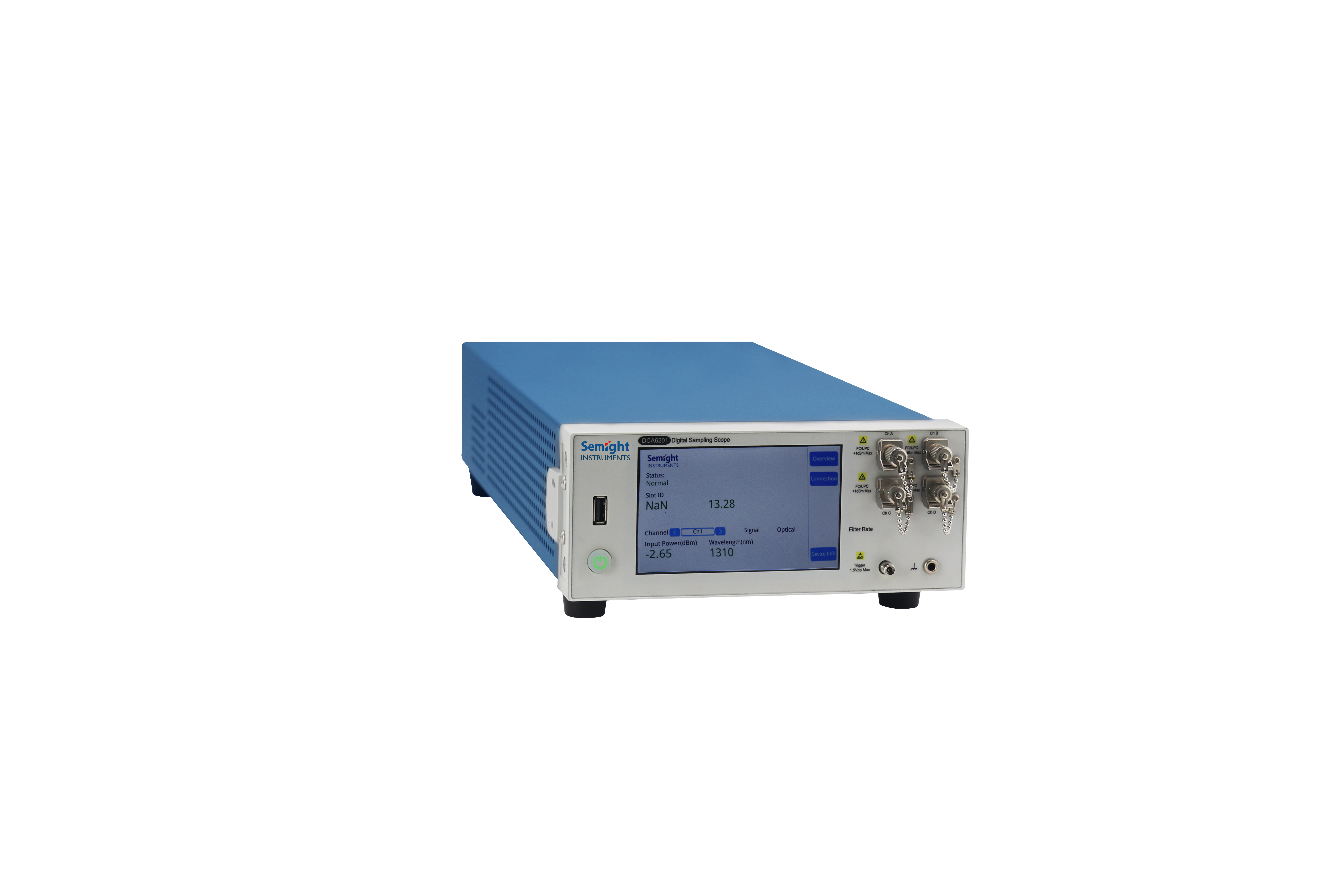
30/50GHz Sampling Oscilloscope DCA6201
Features

Efficient Measurement
Supports simultaneous measurement of all channels and parallel measurement
Multiple Measurement Functions
Meets the normal NRZ and PAM4 eye diagram test parameters
Automatic Test
The remote command control mode is convenient and fast
Ensure Accurate Performance
High performance ensures test consistencyFunctions and Advantages
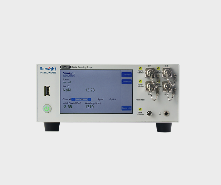
Integrated Multi-port Design
Small size (about 1/4 of the traditional sampling oscilloscope), saves space;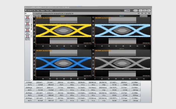
Calibrated Reference Receiver
Comply with the industry frequency response tolerance, compared with the traditional industry standard sampling oscilloscope, the eye diagram shape consistency is very high.As shown in the figure, the NRZ eye diagram
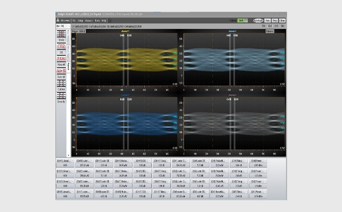
Calibrated Reference Receiver
Comply with the industry frequency response tolerance, compared with the traditional industry standard sampling oscilloscope, the eye diagram shape consistency is very high.Optical Channel Specifications
|
Item |
Specification |
|
|
DCA6201-B30 |
DCA6201-B50 |
|
|
Optical Channel Bandwidth[1] |
30 GHz |
50 GHz(IRC Option) |
|
Fiber Input |
50/125μm FC/UPC (single-mode/ multi-mode) |
|
|
Wavelength Range |
800 - 1650 nm |
|
|
Factory Calibrated Wavelength [2] |
850/1310/1550 nm ±10 nm |
|
|
Supports Various Data Rate According to Multi Standards (Filters)
|
25.78Gbps (25/50/100 Gb Ethernet) 26.56 Gbps (400 Gb Ethernet) 27.95 Gbps (OTU4) 28.05 Gbps (32×Fiber Channel) 26.5625 GBaud PAM4 28.9 GBaud PAM4 |
53.125 GBaud PAM4 53.125 GBaud NRZ 49.7664 GBaud NRZ (50G PON) 24.8832 GBaud NRZ (50G PON) 12.4416 GBaud NRZ (50G PON) |
|
ADC Resolution |
14 Bit |
|
|
Measurement Consistency [3] |
Average Power: ±0.1 dB Extinction Ratio: ±0.3 dB Mask Margin: ±5% TDECQ(PAM4): ±0.5 dB |
|
|
Max Input[4] (Non-Destruction, Peak) |
5 mW (+7 dBm) |
|
|
Sensitivity and Linear Range [5][6] |
NRZ: 0 to -8 dBm PAM4: -1 to -7 dBm |
|
|
Monitor Average Power Range |
-20 dBm to +1 dBm |
|
|
Average Power Monitor Accuracy[7] |
Single-mode ±5% ±200 nW ±connector uncertainty Multimode (characteristic) ± 10% ± 200 nW ± connector uncertainty |
|
|
Input Return Loss (FC/UPC) |
>23 dB@850nm >30 dB@1310nm |
|
[1] Optical channel bandwidth define by optical power reduced by 3dB which is -3dBo bandwidth(-3dBo=-6dBe)
[2] Here the ±10 nm is the source optical wave length error
[3] This parameter is not used to describe instrument specification. It means the difference between test with ideal signal and the theoretical value. In real test scenario, the test consistency related to signal quality
[4] This value is from damage test by increasing the input optical power step by step (0.1dBm step). In real applications, due to the instability of the optical source, please be aware that not to keep the input optical signal power at+7dBm or above. It may cause the instruments performance reduction or even damage
[5] Sensitivity is not a part of instrument specifications. It is calculated from characteristic value of noise. It means the power value when influenced only by oscilloscope‘s noise floor, test with ideal eye diagram mask and the mask margin to be close to 0%. The minimal power value is also related to the quality of signal under test in real scenario
[6] It has difference with different signal(NRZ/PAM4,single-mode/multi-mode)
[7] Due to variations in mode-filling conditions, the measured power in multimode fiber will vary more than the measured power in single-mode fiber. For users needing the most accurate power measurements, use an optical power meter for multimode power measurements
Electrical Specifications
|
Item |
Specification |
|
Electrical Channel Bandwidth [1] |
33 GHz |
|
Input Signal Type |
AC-coupled |
|
Input Connector |
1.85 mm female(Differential) |
|
Dynamic Range of Input |
500 mVpp |
|
DC Accuracy |
3 mV@typ. |
|
RMS Noise |
1.5 mV@typ. |
|
ADC Resolution |
14 Bit |
|
Max Input Amplitude |
±1 V |
|
Impedance |
50±10% Ω |
[1] It's the electrical channel -3dBe bandwidth. It is measured by frequency sweeping after removal of test system(±uncertainty)
Software
Software Introduction
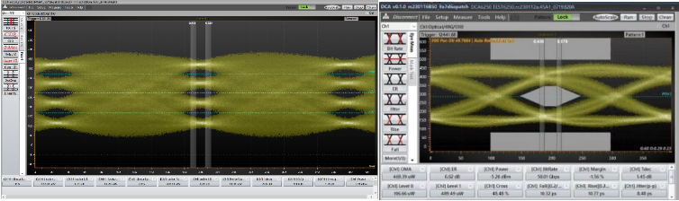
DCA6201 Software Interface
DCA6201 Sampling Oscilloscope Software
Features eye diagram/template measurement functions, installed on a computer or other instruments with a PC hostNotes on previous versions
1. 32-bit and 64-bit installers for A.06.03 and earlier versions (A.06.40 and later versions only support 64-bit operating systems)
2. A.05.80 and earlier versions support 86100C connectivity (86100C must run version A.10.83)
3. A.05.00 and higher supports Windows 7 and Windows 10.
4. A.04.54 and earlier versions support Windows XP
System
Prerequisite
Supported Instruments
Resource Download
 GUI
USB driver
GUI
USB driverSimilar recommendation

High speed communication test plays an important role in the rapid development of big data, cloud computing, 5G communication and other markets.
Semight offers various of instruments for optical Transceiver/Component testing, including wide bandwidth sampling oscilloscope, NRZ/PAM4 bit error ratio tester , burst error ratio tester, fast wavelength meter, high precise source measure unit, 400G network analyzer ,optical power meter, optical attenuator, optical switch etc. We provide cost-effective, complete solutions for optical testing.

The high-precision source measure units integrates the functions of voltage source, current source, voltmeter, ampere meter, and electronic load in one, which is widely used in high-precision IV test and measurement for various discrete components, photovoltaic, green energy, battery and other industries. Semight provides high-precision benchtop SMU and plug-in PXIe SMU of standard PXIe chassis, fully meeting the application of various test scenarios.
Details
Burn-in testing of laser is an important method to ensure the reliability of laser. Through the test of CoC or bare die, the early failure of laser caused by the defects in the process of laser production can be screened out in advance. Semight provides a complete solution from bare die to CoC, from high temperature(150℃ or higher) to low temperature (-40℃), with CoC automatic loading and unloading system, forming a complete test solution, Semight's laser chip burn-in/load/unload test system has been widely recognized by the market.
Details
The semiconductor front-end test is mainly used in the wafer processing to check whether the processing parameters of the wafer products meet the design requirements or there are defects affecting the yield after each step of the manufacturing process. The semiconductor back-end test equipment is mainly used after wafer processing to check whether the performance of the chip meets the requirements, which belongs to the electrical performance test. Semight provides solutions such as Wafer Level Burn In system and Known Good Die handler for SiC testing, offering the value to customer in test efficiency improvement and test cost reduction.
DetailsFollow
Name
E-mail verfication code
Phone
Password
Confirm Password
E-mail address
E-mail verification code
New Password
Confirm Password
 Ask for demo